
A variable frequency drive failure can halt an entire production line within seconds, making it one of the most costly single-point failures in industrial automation. Knowing how to troubleshoot industrial vfd problems quickly is the difference between a 20-minute fix and a 3-day shutdown. This guide from Flexa Systems walks you through every step of the diagnostic process, from reading fault codes to testing output voltage, so you can restore motor speed control before downtime compounds into lost revenue.
Most technicians approach VFD troubleshooting backwards. They swap components first and ask questions later. The better method is systematic diagnosis: read the fault code, verify the supply voltage, test the output terminals, then decide whether you're dealing with a control card issue, a power module failure, or something further upstream in the closed-loop system.
Below, we cover the complete troubleshooting sequence, a multimeter test procedure, a preventive maintenance checklist, and a repair-versus-replace framework. The goal is to give you a decision-making toolkit, not just a list of fault codes.
How to Troubleshoot an Industrial VFD: Where to Start
Effective VFD troubleshooting begins with isolating whether the fault originates inside the drive, in the load (the AC induction motor), or in the supply network. Jumping straight to the drive's internal components without ruling out external causes is the single most common mistake technicians make.
A variable frequency drive is an industrial electronics device that controls motor speed and torque by varying the frequency and voltage supplied to an AC induction motor. When it trips, the fault is rarely random. There is always a root cause, and the drive's built-in diagnostics almost always point toward it.
Safety Precautions Before You Begin
Before touching any terminal or circuit board, follow these steps without exception:
- Isolate the drive from the main supply using the upstream disconnect.
- Wait the manufacturer-specified discharge time (typically 5-15 minutes depending on drive size) for DC bus capacitors to discharge.
- Use a multimeter to verify DC bus voltage is below 50V before opening the enclosure.
- Lock out and tag out (LOTO) the disconnect.
- Wear appropriate PPE: insulated gloves rated for the voltage class, safety glasses, and arc-flash-rated clothing if the enclosure is energized during any live testing phase.
Skipping capacitor discharge is not a judgment call. DC bus voltages in industrial VFDs typically range from 300V to over 700V depending on the drive's power rating.
Tools You Will Need
- Digital multimeter (CAT III or CAT IV rated)
- Clamp-on ammeter
- Insulation resistance tester (megohmmeter)
- Laptop with drive configuration software (brand-specific)
- Thermal imaging camera (optional but highly useful for identifying hot spots on power modules)
- Drive-specific fault code reference manual or manufacturer documentation
VFD Fault Codes List: What Each Code Means
Fault codes are the drive's diagnostic language. Reading them correctly cuts troubleshooting time significantly because each code points to a specific subsystem. According to NEMA's guidelines on variable frequency drive diagnostics, proper fault code interpretation is the foundation of any structured VFD diagnostic process.
Common Fault Codes Across Major Brands
Different manufacturers use different numbering conventions, but the underlying fault categories are consistent across ABB, Allen-Bradley, Siemens, Yaskawa, Schneider Electric, and Danfoss drives.
| Fault Category | Typical Code Examples | Root Cause |
|---|---|---|
| Overcurrent (OC) | F0001, E001, Err 1 | Motor overload, short circuit, rapid acceleration |
| Overvoltage (OV) | F0002, E003, Err 3 | Regenerative braking, supply voltage spike |
| Undervoltage (UV) | F0003, E004, Err 4 | Supply sag, loose input terminal, blown fuse |
| Overtemperature (OH) | F0007, E005, Err 7 | Blocked cooling fan, ambient temp too high |
| Ground Fault (GF) | F0012, E009, Err 12 | Motor insulation failure, damaged output cable |
| Communication Fault | F0070, E070 | Broken fieldbus connection, control card issue |
The most common faults in practice are overcurrent and overtemperature. Overcurrent trips often trace back to the motor or the load, not the drive itself. Overtemperature faults almost always indicate a maintenance issue: a clogged air filter, a failed cooling fan, or an enclosure with inadequate ventilation.
How to Reset an Industrial VFD After a Trip
Resetting without investigating the root cause is a temporary fix that usually results in a repeat trip within minutes. The correct sequence is:
- Record the fault code and any sub-codes before resetting.
- Check the fault history log (most drives store the last 5-10 faults with timestamps).
- Identify whether the fault is persistent (appears every restart) or intermittent.
- Address the root cause.
- Reset via the keypad, digital input, or configuration software as specified by the OEM.
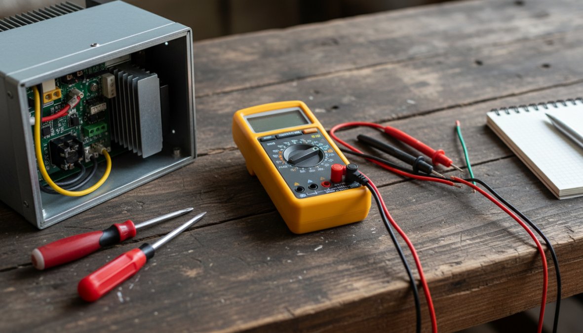
VFD Troubleshooting Multimeter Test: Step-by-Step
A structured VFD troubleshooting multimeter test is the fastest way to confirm whether a drive has internal damage before sending it for component-level repair. This test sequence works on most inverter designs regardless of brand.
Testing Input and Output Terminals
Phase 1: Input diode bridge test (drive de-energized)
Set your multimeter to diode test mode.
- Measure from each input phase terminal (R, S, T) to the positive DC bus terminal (P or +). A healthy diode reads 0.4-0.7V forward bias and OL (open) in reverse.
- Repeat from the negative DC bus terminal (N or -) to each input phase. Expect the same reading pattern.
- A reading of 0V in both directions indicates a shorted diode. A reading of OL in both directions indicates an open diode. Either condition requires component-level repair.
Phase 2: Output IGBT/transistor test
- Measure from the positive DC bus terminal (P) to each output terminal (U, V, W). Expect 0.4-0.7V forward bias.
- Measure from each output terminal to the negative DC bus terminal (N). Same expected reading.
- Any deviation from this pattern suggests a failed power module or IGBT.
Phase 3: DC bus capacitor pre-charge check
With the drive energized at rated input voltage, measure DC bus voltage between P and N. It should be approximately 1.35 times the line-to-line input voltage (e.g., 480V AC input gives roughly 648V DC bus). A significantly lower reading suggests a failing pre-charge resistor or capacitor bank.
How to Test VFD Output Voltage Accurately
Testing VFD output voltage requires a true-RMS multimeter because the drive's output is a pulse-width modulated (PWM) signal, not a clean sine wave. Standard average-responding meters give inaccurate readings on PWM outputs, which is a detail many guides miss entirely.
Interpreting Output Voltage Readings
With the drive running at a known output frequency, measure phase-to-phase voltage between U-V, V-W, and U-W output terminals.
What to look for:
- All three phase-to-phase voltages should be balanced within 2-3% of each other. Significant imbalance points to a failed output phase on the power module or a damaged terminal card.
- Output voltage at rated frequency should be close to input voltage (for standard V/Hz control). A large discrepancy suggests a control card or gate driver issue.
- If any output phase reads zero while the others are normal, the drive has a confirmed power module fault on that phase.
A clamp-on ammeter measuring output current on each phase provides complementary data. Balanced voltage with unbalanced current typically indicates a motor winding issue, not a drive fault. This distinction matters for deciding whether the drive or the motor needs attention.
Preventive Maintenance for Variable Frequency Drives
Preventive maintenance for variable frequency drives is the most cost-effective strategy for extending drive life and avoiding unplanned downtime. Most VFD failures that reach the repair bench were preventable with a structured inspection program.
Scheduled Inspection Checklist
The following checklist covers the maintenance tasks that catch the majority of developing faults before they become trips:
Monthly:
- Inspect and clean air filters and ventilation openings
- Verify cooling fan operation (listen for bearing noise, check airflow)
- Check enclosure temperature against ambient conditions
- Inspect terminal connections for corrosion or discoloration
- Review fault history log for any new entries
Quarterly:
- Torque-check all power terminal connections (loose terminals cause overheating and arcing)
- Inspect output cables and motor connection for insulation damage
- Verify control wiring integrity on terminal cards
- Run a basic load test and compare output current to baseline
- Check DC bus capacitor voltage against specification (if accessible)
Annually:
- Perform insulation resistance test on motor and output cables
- Replace air filters
- Inspect capacitor banks for swelling or electrolyte leakage
- Review and update drive firmware if OEM has issued updates
- Conduct full load testing under actual operating conditions
As documented in IEEE's recommended practices for industrial power electronics maintenance, capacitor degradation is the leading cause of age-related VFD failure, and it is detectable through routine inspection well before catastrophic failure occurs.
Repair vs. Replace: A Cost-Benefit Framework for VFDs
The default instinct when a drive fails is to order a replacement. That instinct is expensive and often unnecessary, but so is repairing a drive that is genuinely at end-of-life. The decision deserves a structured framework, not a gut call made under downtime pressure.
No competitor currently offers a practical decision model for this. The section below gives you one.
The Four Variables That Drive the Decision
Every repair-versus-replace decision comes down to four inputs:
- Repair cost as a percentage of new-unit cost, The widely used industry threshold is 50%. Below that, repair is almost always the right economic choice. Above 60-65%, the math starts favoring replacement, especially on older units.
- Drive age relative to expected service life, A well-maintained VFD in a clean environment has a realistic service life of 15-25 years. A drive at year 18 with a failed power module is a different risk profile than the same fault on a 4-year-old unit. Age alone is not disqualifying, but it changes the probability of a second failure within 12-24 months.
- Parts availability and OEM support status, When a manufacturer discontinues a drive platform, spare IGBT modules, control cards, and gate driver boards eventually become scarce. If a component-level repair requires a part that is already on allocation or only available from secondary markets, factor in both the cost premium and the lead time risk.
- Downtime cost per day for your specific application, This is the variable most facilities never calculate explicitly, but it is the most important one. A VFD on a non-critical exhaust fan has a very different downtime cost than a VFD on the only extruder in a production cell. If your downtime cost is high, the decision calculus shifts toward whichever path restores operation fastest, which is often repair on a drive with a known fault, not a new unit with a 12-16 week lead time.
A Practical Decision Matrix
Use this matrix as a starting point. It is not a substitute for a formal quote, but it gives you a defensible first-pass answer before you have one.
| Condition | Repair Signal | Replace Signal |
|---|---|---|
| Drive age | Under 12 years | Over 18 years with multiple prior repairs |
| Fault type | Single subsystem (power module, control card, or capacitor bank) | Multiple simultaneous subsystem failures |
| Repair cost vs. new unit | Below 50% | Above 65% |
| OEM support status | Active, parts available | Discontinued, parts on allocation |
| Lead time on new unit | Under 4 weeks | Over 8 weeks (favors repair regardless of cost) |
| Fault history | First or second repair in drive's life | Third or more repair within 5 years |
| Application criticality | Non-critical or redundant | Single-point-of-failure, no spare |
When multiple rows in the "Replace Signal" column apply simultaneously, replacement is the right call. When the signals are mixed, repair is usually the lower-risk path, provided the repair facility performs component-level work with a meaningful warranty rather than a board swap.
The Lead Time Factor: Why It Changes Everything in 2024-2026
New VFD lead times from major OEMs have ranged from 8 weeks to over 30 weeks for certain power ratings and configurations during recent supply chain disruptions. A component-level repair on a known fault, by contrast, typically completes in 2-10 business days at a qualified facility, with rush options available for critical applications.
This asymmetry means that even when the cost comparison is close, say, repair at 55% of new-unit cost, the lead time difference alone can justify repair when downtime cost is significant. A facility losing meaningful production revenue per day of downtime will recover the cost difference between repair and replacement within days of restored operation.
The Sustainability Case for Repair
For facilities with sustainability reporting requirements or ESG commitments, the repair-first decision has a measurable environmental dimension that replacement does not.
Manufacturing a new industrial VFD requires raw material extraction, component fabrication, and global logistics, all of which carry an embedded carbon cost. Repairing an existing unit at the component level preserves the vast majority of that embedded value. According to the U.S. Environmental Protection Agency's guidance on industrial electronics and e-waste, repairing and refurbishing industrial electronics reduces both landfill burden and the energy cost of new manufacturing.
For facilities that report under frameworks such as GHG Protocol Scope 3 or that have committed to circular economy principles, choosing repair over replacement on a recoverable drive is a documentable, quantifiable action, not just a cost decision.
What a Legitimate Repair Quote Should Include
Not all repair quotes are equivalent. A quote that covers only the presenting fault, the component that caused the trip, without inspecting adjacent subsystems is a short-term fix. A thorough component-level repair should include:
- Full diagnostic report identifying the root cause, not just the failed component
- Inspection of DC bus capacitors for capacitance loss and ESR degradation (not just visual inspection)
- Thermal imaging or load testing to verify power module health beyond the faulted phase
- Firmware verification and parameter backup
- A written warranty on parts and labor, industry standard is 12-24 months on completed repairs
Flexa Systems provides free incoming diagnostics on all received units, which means you get a full fault report and repair estimate before committing to any cost. Component-level repair with a 2-year warranty eliminates the guesswork from the repair-versus-replace decision.
How to Troubleshoot Industrial VFD Issues by Brand
Brand-specific knowledge matters because each manufacturer implements fault handling, parameter structures, internal protection logic, and diagnostic tooling differently. The same symptom, an overcurrent trip, for example, requires a different diagnostic path on an ABB ACS880 than on a Yaskawa GA700 or a Siemens SINAMICS G120. This section goes beyond fault code tables to give you the platform-specific details that actually save time on the bench.
ABB Drives (ACS355, ACS580, ACS880 Series)
Diagnostic tool: Drive Composer Entry (free) or Drive Composer Pro (licensed). Connect via USB or Ethernet depending on the unit generation.
What makes ABB different: ABB drives generate both a primary fault code and a sub-code that identifies the specific internal protection that triggered. The sub-code is the more useful number. An overcurrent fault (code 2310 on ACS880) with sub-code 1 points to an output phase short, while sub-code 5 points to an earth fault detected at the output stage, two very different root causes requiring different corrective actions.
Common failure pattern: On ACS580 and ACS880 units, overcurrent faults that cannot be traced to the motor or cable frequently originate at the IGBT gate driver board rather than the IGBT module itself. The gate driver is a lower-cost component than the power module, and misdiagnosing it as a full power module failure is a common and expensive error. Testing gate driver output signals with an oscilloscope before condemning the IGBT stack is worth the extra 20 minutes.
Fault logger: Drive Composer captures a parameter snapshot at the moment of fault. Export the fault logger data before resetting, it records output frequency, DC bus voltage, output current on all three phases, and heatsink temperature at the fault instant.
Allen-Bradley Drives (PowerFlex 40, 525, 755, 755T Series)
Diagnostic tool: Connected Components Workbench (CCW) for PowerFlex 40/525; Studio 5000 Logix Designer or the PowerFlex 755 Add-On Profile for 755/755T series.
What makes Allen-Bradley different: PowerFlex drives store a fault queue (typically the last 8 faults) with a timestamp and a parameter snapshot for each entry. The parameter snapshot includes output current, output voltage, DC bus voltage, and drive temperature at the moment of each fault. Reviewing the trend across multiple fault entries, not just the most recent one, often reveals a pattern that points to a developing hardware issue before it becomes a hard failure.
Common failure pattern: Ground fault faults (Fault 13 on PowerFlex 755) on drives with otherwise healthy power modules most commonly trace to the motor cable rather than the drive's internal circuitry. Perform an insulation resistance test on the output cable and motor before opening the drive enclosure. A megohmmeter reading below 1 MΩ phase-to-ground on the cable confirms the fault is external.
PowerFlex 755T-specific note: The 755T series includes an integrated active front end (AFE). Communication faults on 755T units sometimes reflect a synchronization issue between the inverter and converter sections rather than a fieldbus problem. Check the AFE status parameters (parameter group 6 in the 755T parameter set) before investigating the network connection.
Siemens Drives (SINAMICS G120, G120C, S120 Series)
Diagnostic tool: STARTER (legacy) or Startdrive (TIA Portal integrated). Startdrive provides oscilloscope-style trace recording with configurable trigger conditions, a capability that is genuinely useful for capturing intermittent faults.
What makes Siemens different: SINAMICS drives use a two-tier fault/alarm system. Faults (Fxxxx codes) cause a trip and require acknowledgment. Alarms (Axxxx codes) are advisory and do not trip the drive. Technicians who focus only on fault codes and ignore the alarm history miss early warning signals. An A07910 alarm (motor overtemperature model) appearing repeatedly before a hard fault is a diagnostic clue, not background noise.
Common failure pattern: Communication faults on SINAMICS G120 units in PROFINET configurations frequently trace to IP address conflicts or incorrect device naming in the network configuration rather than hardware failure. Before suspecting the Control Unit (CU230P-2 or CU240E-2), verify the PROFINET device name matches the hardware configuration in TIA Portal exactly, including case sensitivity.
S120 booksize units: The S120 architecture separates the Control Unit from the Motor Module. A fault that appears on the Control Unit display may originate in the Motor Module or the Line Module. Always check the diagnostic buffer on each component separately using Startdrive's component-level view.
Yaskawa Drives (A1000, GA700, GA800 Series)
Diagnostic tool: DriveWizard Industrial (desktop) or DriveWizard Mobile (iOS/Android via Bluetooth on GA700/GA800). DriveWizard provides parameter management, fault history export, and a parameter comparison function that is useful for verifying a repaired drive's configuration against a known-good backup.
What makes Yaskawa different: Yaskawa fault sub-codes are among the most granular in the industry. An oC (overcurrent) fault on a GA700 carries a sub-code that distinguishes between overcurrent during acceleration, during deceleration, during constant speed, or at startup, each pointing to a different root cause. Treating all oC faults as equivalent wastes diagnostic time.
Common failure pattern: On A1000 units operating in high-cycle applications (frequent starts and stops), the pre-charge relay is a common wear item. A UV (undervoltage) fault that appears at startup but clears on retry, combined with a DC bus voltage that rises slowly rather than snapping to the expected value, is a strong indicator of a failing pre-charge relay or pre-charge resistor rather than a supply voltage problem.
GA700/GA800 note: These platforms support DriveCloud parameter backup. If a GA700 fails and a replacement unit is available, parameter restoration from a cloud backup takes minutes rather than the hours required for manual re-entry on older platforms.
Schneider Electric Drives (Altivar 312, 630, 930 Series)
Diagnostic tool: SoMove software (PC) or the EcoStruxure Power Commission app for newer Altivar Process series drives.
What makes Schneider different: Altivar drives in the 630 and 930 series include an embedded webserver accessible via Ethernet that provides real-time parameter monitoring and fault history without requiring a laptop with installed software. This is useful for remote diagnostics on drives installed in hard-to-access locations.
Common failure pattern: On Altivar 312 units, internal fan failure is a frequent cause of overtemperature faults (OHF code) in drives that are otherwise mechanically sound. The 312's internal fan is a low-cost component but requires enclosure opening to replace. Because the fault presents identically to an ambient temperature problem, always verify fan operation before investigating the installation environment.
Danfoss Drives (VLT AutomationDrive FC 302, Vacon 100 Series)
Diagnostic tool: MyDrive Suite (cloud-connected, browser-based) for FC 302 and newer Vacon platforms. Older Vacon units use VACON Live PC software.
What makes Danfoss different: The FC 302 stores a 500-event fault and warning log with millisecond timestamps. For intermittent faults that are difficult to reproduce, this log depth is valuable, it allows correlation of fault events with process conditions over days or weeks rather than just the last few trips.
Common failure pattern: On FC 302 units in pump and fan applications using cascade control, alarm 69 (power card temperature) sometimes appears without a genuine overtemperature condition. Verify the power card temperature sensor reading against the actual heatsink temperature using a contact thermometer or thermal camera before condemning the power card.
When Brand-Specific Repair Matters for Warranty
For drives still under OEM warranty, component-level repair must be performed by an authorized service provider to preserve warranty coverage. For out-of-warranty units, the more important credential is ISO 9001:2015 certification and documented adherence to OEM component specifications, not brand authorization itself. A repair facility working to OEM specifications with traceable components produces a repaired unit that performs to the same standard as factory service, regardless of authorization status.
VFD Lifecycle Management and Sustainability Considerations
A variable frequency drive has a functional service life of 15-25 years under normal operating conditions, but that lifespan depends heavily on maintenance quality and operating environment. Lifecycle management means planning for the full service life rather than reacting to each failure in isolation.
Practical lifecycle management looks like this:
- Track fault history and repair history for each drive in your facility. Drives that have been repaired more than twice in five years are candidates for proactive replacement before a critical failure.
- Monitor DC bus capacitor health annually after year 10. Electrolytic capacitors degrade with age and thermal cycling, and their failure mode is often sudden rather than gradual.
- Maintain a spare drive inventory for critical applications. A refurbished unit from a reputable repair facility costs a fraction of a new unit and can be configured to match the failed drive's parameters.
- Plan for obsolescence. When a drive platform is discontinued by the manufacturer, source spare boards and power modules while they are still available.
The energy efficiency case for VFDs is well-established. As referenced in the U.S. Department of Energy's resources on motor systems and variable speed drives, variable frequency drives on pump and fan applications typically reduce energy consumption significantly compared to fixed-speed operation, which makes keeping existing drives operational a direct contributor to energy efficiency goals.
From a sustainability perspective, the repair-first approach to VFD lifecycle management aligns with circular economy principles. Extending the service life of an existing drive through component-level repair avoids the full manufacturing energy cost of a new unit, reduces electronic waste, and preserves the embedded value of the original equipment.
Flexa Systems handles VFD lifecycle management for clients nationwide from their base in Lewisville, TX, offering 24-72 hour rush service for critical applications alongside standard turnaround times that minimize operational downtime.
Frequently Asked Questions
What are the most common causes of VFD failure?
The most common causes of VFD failure include overheating due to blocked cooling vents, voltage spikes or power surges damaging power modules, contamination from dust or moisture on circuit boards, loose terminal connections, and capacitor degradation over time. In many cases, early warning signs like erratic motor speed control or repeated fault trips appear before a complete failure. Routine preventive maintenance and prompt attention to fault codes can significantly extend the life of a variable frequency drive.
How do you test a VFD with a multimeter?
To perform a VFD troubleshooting multimeter test, first isolate and de-energize the drive and wait for DC bus voltage to discharge. Set your multimeter to DC voltage mode and check the DC bus capacitors for residual charge. Then switch to diode-test mode to check the input rectifier diodes and output IGBT power modules for shorts or open circuits. Finally, use AC voltage mode with the drive powered to verify balanced three-phase output voltage to the AC induction motor terminals.
What does a VFD fault code mean and how do I find it?
A VFD fault code is an alphanumeric error displayed on the drive's keypad or HMI that identifies a specific problem detected by the drive's internal diagnostics. Common codes cover overcurrent, overvoltage, undervoltage, overtemperature, and ground faults. Each brand, including ABB, Allen-Bradley, Siemens, Yaskawa, Danfoss, and Schneider Electric, uses its own fault code list, so always consult the specific drive's manual. Documenting fault history helps during failure analysis and component-level repair.
Can a VFD be repaired, or should it be replaced?
In most cases, a VFD can be repaired at a fraction of the cost of replacement. Component-level repair targeting failed circuit boards, control cards, or power modules can save up to 70% compared to buying new equipment. Replacement makes more sense when the drive is obsolete with no parts availability, has sustained catastrophic physical damage, or repair costs exceed roughly 60-70% of new unit cost. A qualified repair facility offering free diagnostics and a warranty can help you make an informed repair vs. replace decision.
How often should I perform preventive maintenance on a variable frequency drive?
Preventive maintenance for variable frequency drives is generally recommended every 6 to 12 months depending on the operating environment. Key tasks include cleaning cooling fans and heat sinks, inspecting terminal connections for tightness, checking capacitor condition, verifying firmware and parameter settings, and performing load testing. Drives in harsh environments with high dust, humidity, or temperature extremes may require more frequent inspections. A consistent PM schedule reduces unplanned downtime and extends the overall lifecycle of the inverter.
Unplanned VFD downtime rarely announces itself, and the cost compounds quickly when a critical motor goes offline. Flexa Systems specializes in component-level repair of VFDs, PLCs, HMIs, and servo drives, with free diagnostics on every unit received, a 2-year warranty on all completed repairs, and 24-72 hour rush service for time-sensitive situations. Get a quote from Flexa Systems and keep your industrial automation running without the cost of new equipment replacement.